“The LDE series is an on-board dual-in-line package AC/DC module power supply, which is widely used in many fields such as industry, electric power, instrumentation, communication and intelligent buildings.
“
The LDE series is an on-board dual-in-line package AC/DC module power supply, which is widely used in many fields such as industry, electric power, instrumentation, communication and intelligent buildings.
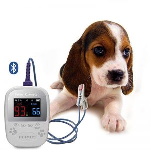
The Electronic pulse meter takes out the “finger pulse” signal from the finger, which is very convenient to use. When the tip of the finger is slightly compressed, you can feel the tip of the finger relaxes under the action of blood pressure. This signal is extracted by the sensor, converted into an electrical signal, and then displayed in the form of light and sound. I know the pulse is beating.
In order to facilitate frequent carrying and production, this machine only uses a CMOS integrated circuit and a triode. The quiescent current is only 10-20μA, and the power consumption is small, so the whole machine only uses two AG10 button batteries. The electrical schematic diagram of the electronic pulse meter is shown in the figure. It is composed of sensor (B), amplifier, shaping circuit and driving circuit. The whole circuit is composed of 4 CMOS NAND gates to form amplifying, shaping and oscillating circuits. A sensor made of piezoelectric ceramics at the front end converts the pulsating pressure signal on the finger into an electrical signal.
Amplification circuit: Since the electrical signal sent by the sensor is extremely weak, an amplifying circuit with high input impedance must be used. If the CMOS inverter is used as an analog device, as long as the appropriate linear bias is added, it is a high impedance amplifier with good performance, such as YF1 in Figure 28-1. A resistor R5 is used to connect the input terminal and output terminal of the inverter YF1, which is both a feedback resistor and a bias resistor. This constitutes an amplifier with negative feedback. The function of the capacitor C1 is a high-frequency bypass to prevent self-oscillation.
Shaping circuit: The second stage uses inverter YF2 as the shaper. This stage works in the on-off state, so no bias is added. If the output level of YF1 is higher than the turn-on level of YF2, YF2 will output a low level; if it is lower than the turn-on level of YF2, YF2 will output a high level. Since the value of the feedback resistor R5 of the first-stage amplifying circuit is selected properly, the output of YF1 just exceeds the turn-on level of YF2. Once the sensor has a weak signal output, after YF1 amplification, YF2 output high level after shaping. YF2 outputs low level in static state.
Audio and LED drive circuit: YF3 and YF4 form a controlled multivibrator. When YF2 outputs a high level, the oscillator starts to oscillate. Adjusting resistors R1, R2 and capacitor C2 can change the oscillation frequency. At the same time, YF3 drives the piezoelectric ceramic chip BC to emit sound, and YF4 connects the transistor VT1 to drive the light-emitting diode to emit light.
In addition to the circuit part of the electronic pulse meter, the quality of the sensor will directly affect the sensitivity of the instrument, so the production of the sensor is a very important part. The ceramic side of the piezoelectric ceramic sheet is welded to the copper ring side (three points uniformly welded on the circumference), a thin shielded wire is used as the lead wire, the outer skin is connected to the copper ring, and the core wire is welded through the copper ring gap On the ceramic surface. Then weld a copper sheet under the copper ring and weld it well.
Finally, according to the thickness of ordinary people’s fingers, a piece of metal watch with springs is cut out and connected to the sensor, and formed into a circle so that it can be put on the finger during use. The piezoelectric ceramic sheet used in the sensor is HTD-20, but the following requirements should be paid attention to when selecting piezoelectric ceramic sheet: connect the silver-plated ceramic surface to the Y-axis input terminal of the oscilloscope, the ground terminal of the metal substrate, and touch the metal substrate with your hand On the one hand, observe the silver-plated side, the output should be positive pulse before it can be used.
The electronic pulse meter does not have a power switch. When using the sensor, first touch the sensor with your finger, and the instrument will emit a “ji, chi” sound, and the luminous tube will emit red light, indicating that the instrument is working normally. Wear the sensor on your finger to feel a little pressure, and wait for a while (because it takes a while for the blood flow to flow back into the finger after the finger is compressed), the instrument will emit a sound and Display a red light with the pulse.
The Links: G057QN01-V2 TPS53515RVER